In other posts from this series, I’ve shown you how to install Octoprint and how to make your printer more silent and precise. Since these modifications to my own printer, I’ve found an issue with my heated bed. The built-in control circuitry was not up to the task of precisely controlling my heated bed temperature using PID. My printer ships with a bang-bang control system, which is less demanding on the heater MOSFET. My upgraded firmware demanded more of the hardware, which started failing.
Why upgrade the MOSFET?
The heated bed uses a lot of power to heat up a large surface. All this power goes through aMetal Oxide Silicon Field Effect Transistor (MOSFET, which is a piece of solid-state electronics. It basically works like a switch, but instead of being controlled mechanically (flicking it), it is controlled electronically (a small voltage and current used for switching). The benefit of this is that we can use a low power thing, like a microcontroller, to switch something power-hungry like a heated bed. The downside is that the MOSFET heats up because of the power going through it.
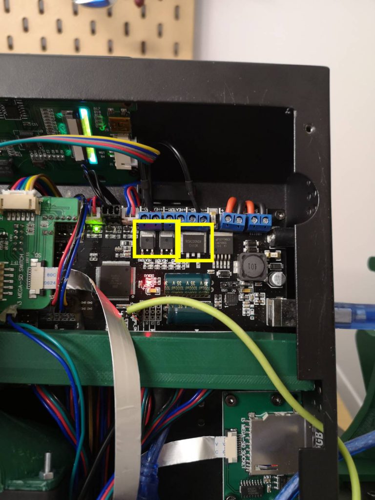
My printer shipped with a few MOSFETs on the control board, you can see these below. These MOSFETs have no heatsink or active cooling. This means that the parts are constantly very hot, with nowhere to put the heat. An upgrade is desperately needed. Note that online this upgrade is often referred to as “installing a MOSFET”, but that’s incorrect. I am simply replacing the ones I had with better ones.
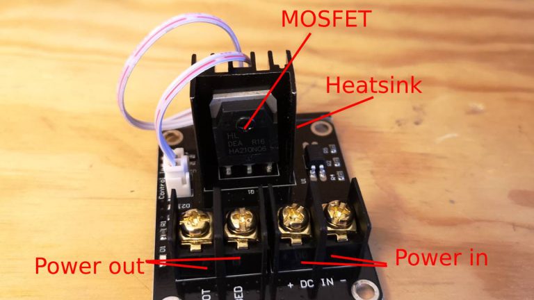
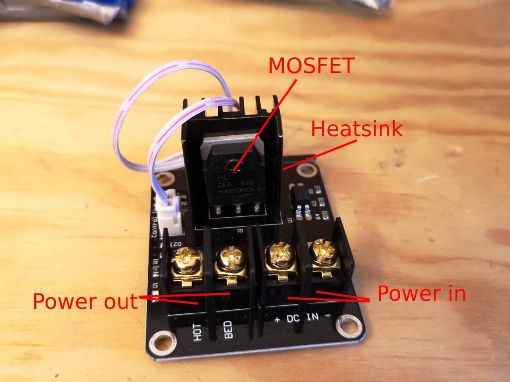
In comes the MOSFET breakout board (see below). This is a separate MOSFET on a nice little PCB, with a heat sink, and thick screw-terminals.
The upgrade
You’ll need to connect the MOSFET to power, to the heated bed, and to the control signal. The white wire that shipped with the MOSFET is the signal wire (which I had to extend).
I have already done some modifications to my printer, which made me unable to use this bracket, but it is a very elegant solution if you have space. In my case, I had installed a Raspberry Pi that was in the way, so I opted for another solution.
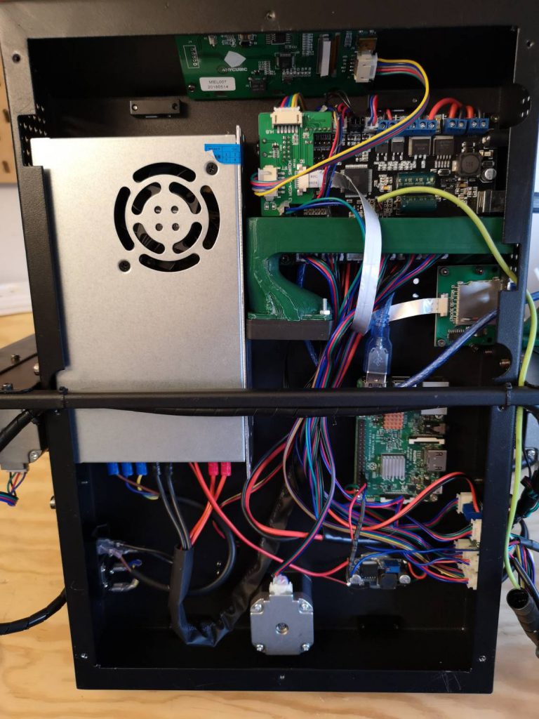
I simply hot-glued the MOSFETs in place, making sure no metal parts are touching the metal case of the printer. While I was in there I upgraded my hotend MOSFET, since the parts are cheap, and I had the printer open anyway.
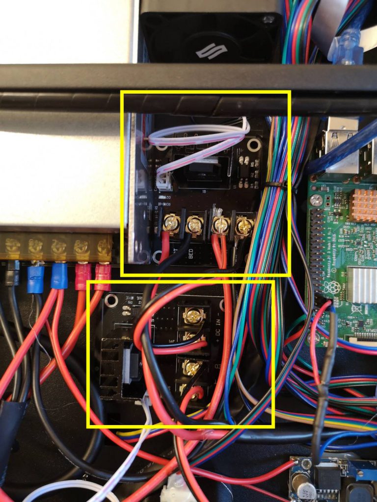
The picture shows the wires already connected, which I used this very handy video guide for. Connecting the wires is actually easier than it looks. The power-in side of the MOSFET has a polarity (+ and -), but the other wires don’t care how they’re connected. You want to connect the power-in “+” to the power-supply “+” and the power-in “-” to the power-supply “-“. The heated bed and hotend are simple resistors, so “+” and “-“can be switched. The white cable that comes with the MOSFET is the signal wire, this connects to the old terminals where the heated bed and hotend connected to before.
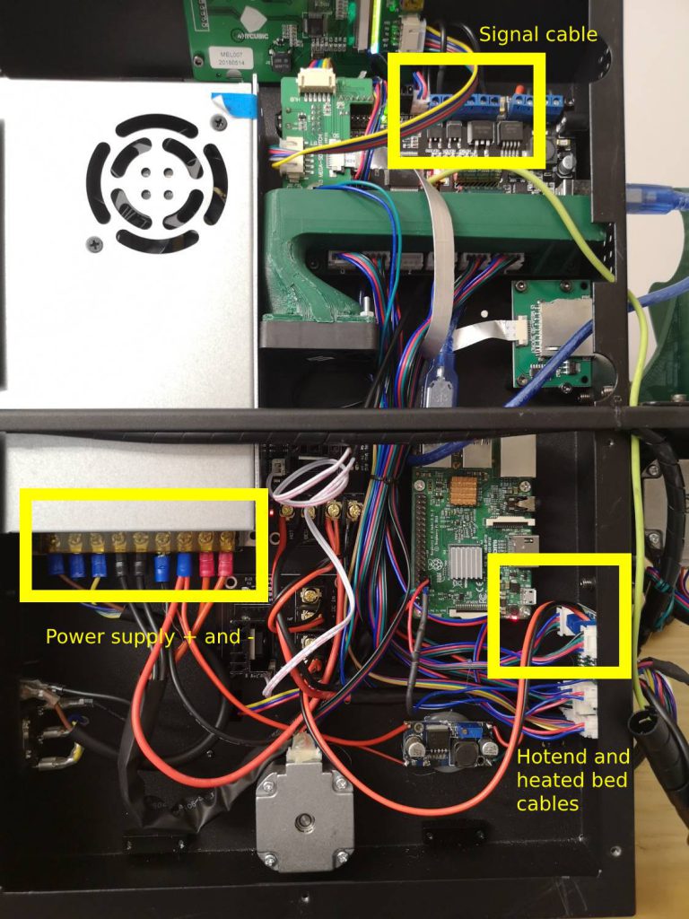
Hotend and heated bed cables connect to the left terminals (no polarity)
Signal cables connect to the old terminals
Setting up the firmware
In Marlin, in Configuration.h is the thermal management segment (starts at line 398). The bed has a bang-bang control as standard, uncommenting “//define PIDTEMPBED” will enable PID control for the bed.
You will need to tune the PID settings, luckily there’s an autotune module inside Marlin. This needs to be called from the Gcode terminal of your favorite printing software (I use Octoprint). To perform autotune, make sure your heated bed is empty (no tools or parts on there!) and type M303 E-1 S50 C6 U1 to start heated bed PID auto-tuning at 50 degrees C.
This will take a while, and when completed will provide you with the PID values. These values need to be copied into Marlin. After this, compile Marlin and reflash your printer.
That’s it
You now have a more reliable and better heat control for your printer. Enjoy the upgrade and post any questions in the comments!
